How to create Dataflows
Data flows can be defined at three different levels:
- Flow between system and system: Shows the interaction and dependencies between different systems.
- Flow between entities and entities: Reveals the interaction between various data structures (tables, files, etc.) of the systems involved.
- Flow between attribute and attribute: The most detailed level, enabling the representation of precise data interactions.
This chapter explores the main ways to create data flows: manual definition in the UI, bulk CSV import, automated ingestion through agent crawling jobs (SQL strategy), and SQL statement analysis.
Single dataflow creation
To define a Data Flow manually, click on the button in the main page. This button opens the Data Flow definition modal, where you can specify:
- Name: the name of the data flow.
- Scope: the range of data that the data flow covers.
- Description: the description of the data flow.
- From/To: allows the definition of the data flow at three possible levels, specifying the system, physical entity, and physical field of origin and destination.
- Concepts: the concepts connected to the data flow.
- Attributes: the attributes connected to the data flow.
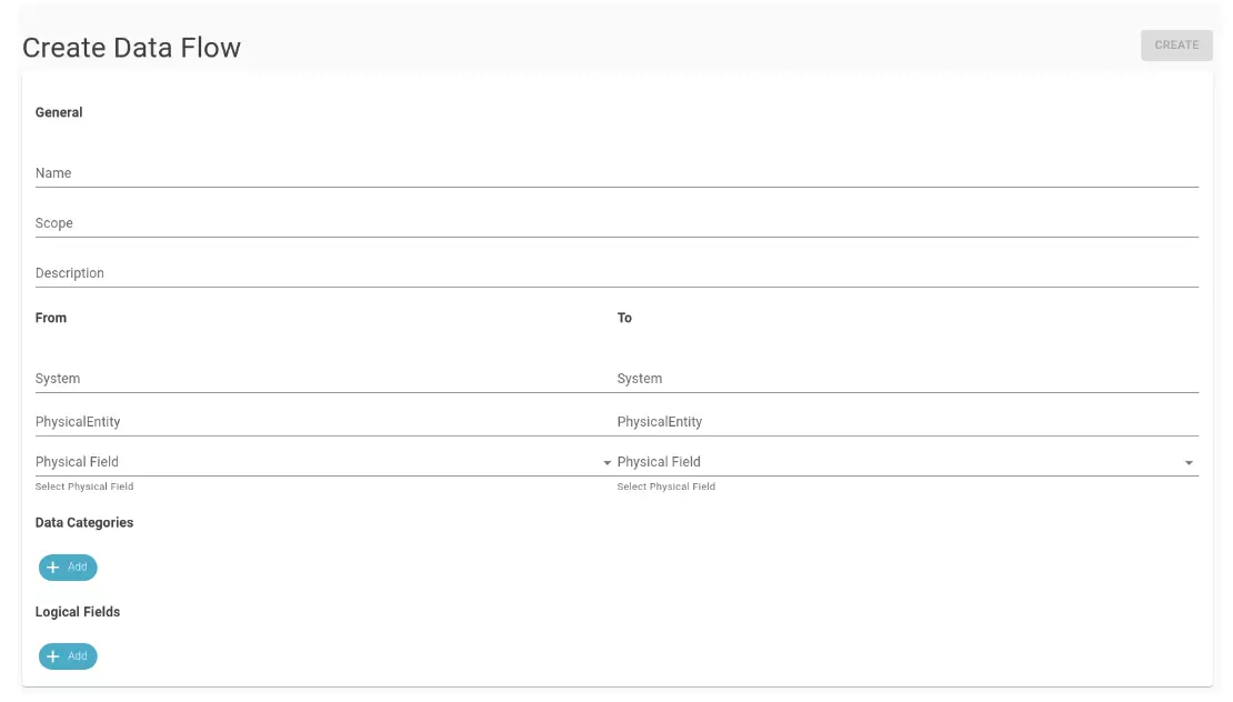
Upon completion, clicking the “Create” button in the upper right corner (as shown in the previous figure) finalizes the data flow creation.
Connection of two physical entities
Another manual method for creating data flows involves the Data Flow panel on the Physical Entity detail page. Within the “Dataflows” tab of the detail page of a physical entity, it is possible to manually link another physical entity through the buttons above Incoming/Outcoming, as shown in the figure.
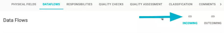
The difference between the two is in the positioning of the catalog element under examination: Incoming: links another catalog element as incoming to the one we are in. Outcoming: links the element to another as outgoing, i.e. starts the link from the element we are in to a selected one. The selection modal is the same for both buttons, only the section representing the current physical entity changes.
INCOMING
OUTCOMING
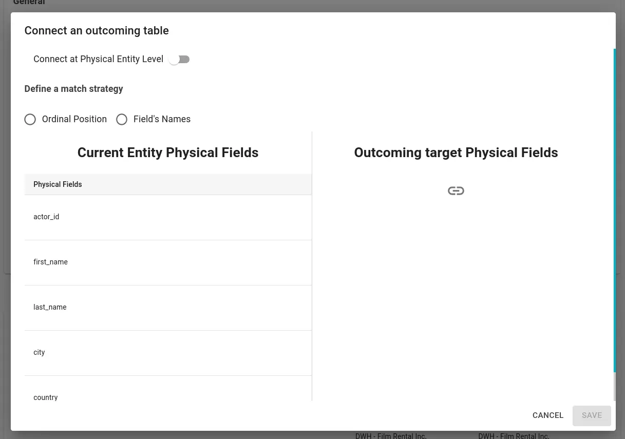
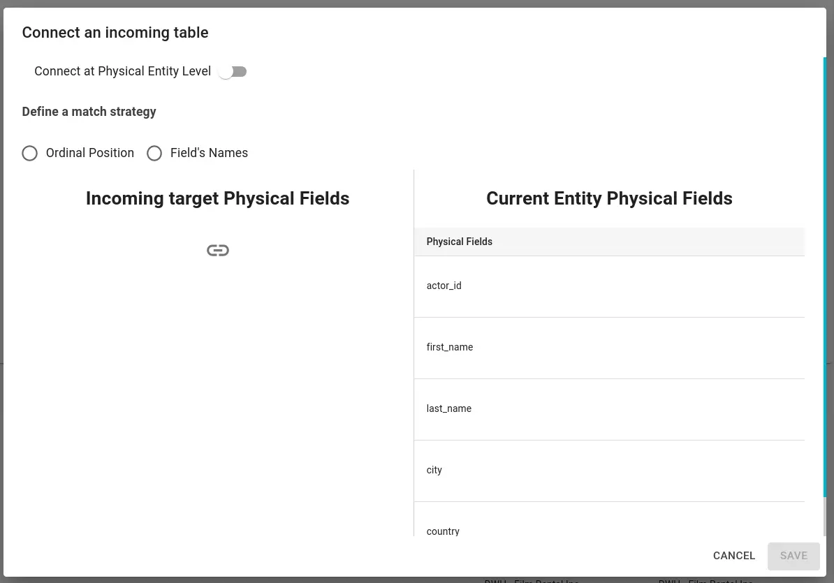
Through the “connect a Physical Entity Level” switch, it is possible to choose whether to generate data flows between physical fields or to generate a single data flow between the two physical entities.
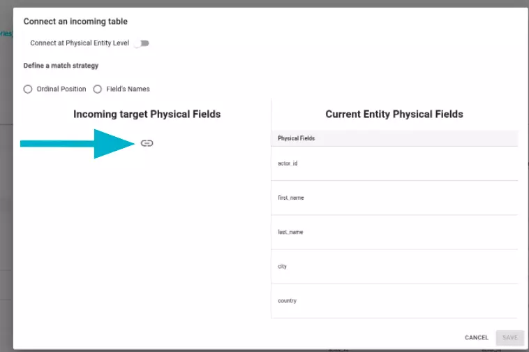
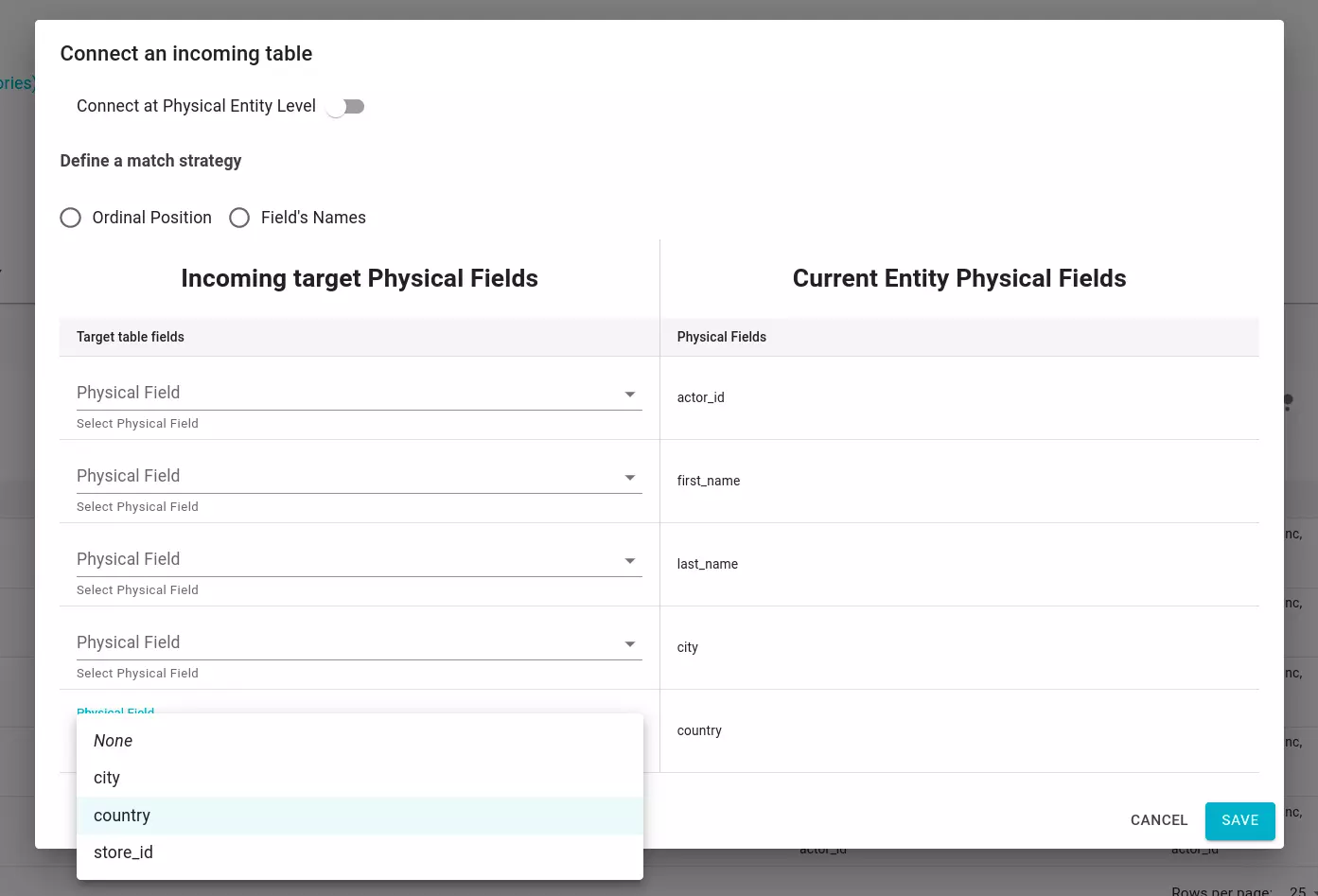
Clicking on the icon shown in the figure opens the physical entities search modal. Once the physical entity is selected, it is possible to map the physical fields with three different strategies:
- Ordinal Position: physical fields are mapped based on the “Ordinal Position” attribute.
- Field’s Name: physical fields are mapped based on their name.
- Manual: you manually choose the physical field you want to connect.
Massive import via CSV file
To further enhance flexibility, data flows can also be created by uploading a CSV file. For an example of the track record, download it from the Data Flow Registry page.
Tip
If numerous dataflows are available and you only want CSV file as an example, it’s advisable to filter the dataflows into a smaller subset before downloading them. This approach can significantly expedite the download process.
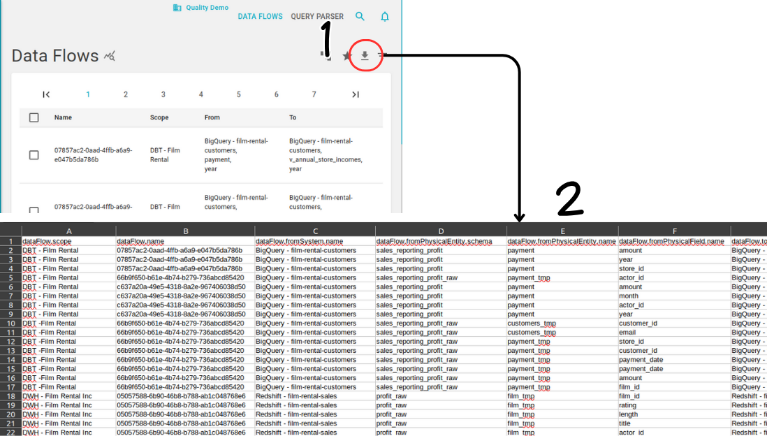
Once downloaded, the CSV file can be edited to modify already present dataflows or simply add new ones. Each column of the CSV file represents a field of the dataflow.
- dataFlow.scope: the scope serves as a tag to distinguish dataflows by the process or entity that loads them onto Blindata. It, along with the name, forms the dataflow’s identifier.
- dataFlow.name: this is the name of the dataflow, used in conjunction with the scope to identify it uniquely.
- dataFlow.fromSystem.name: the name of the system from which the dataflow originates.
- dataFlow.fromPhysicalEntity.schema: the schema of the physicalEntity from which the dataflow originates.
- dataFlow.fromPhysicalEntity.name: the name of the physicalEntity from which the dataflow originates.
- dataFlow.fromPhysicalField.name: the name of the physicalField from which the dataflow originates.
- dataFlow.toSystem.name: the name of the system to which the dataflow ends.
- dataFlow.toPhysicalEntity.schema: the schema of the physicalEntity to which the dataflow ends.
- dataFlow.toPhysicalEntity.name: the name of the physicalEntity to which the dataflow ends.
- dataFlow.toPhysicalField.name: the name of the physicalField to which the dataflow ends.
- dataFlow.description: a brief description of the dataflow.
- dataFlow.[..].fullName: a different representation of the information. It should be omitted when a dataflow is modified or created.
- dataFlow.[..].queryStatement: the SQL statement that originates the dataflow. It is a read only information and should not be modified manually.
- dataFlow.[..].uuid: the internal identifiers of Blindata. They can be omitted when modifying or creating new dataflows.
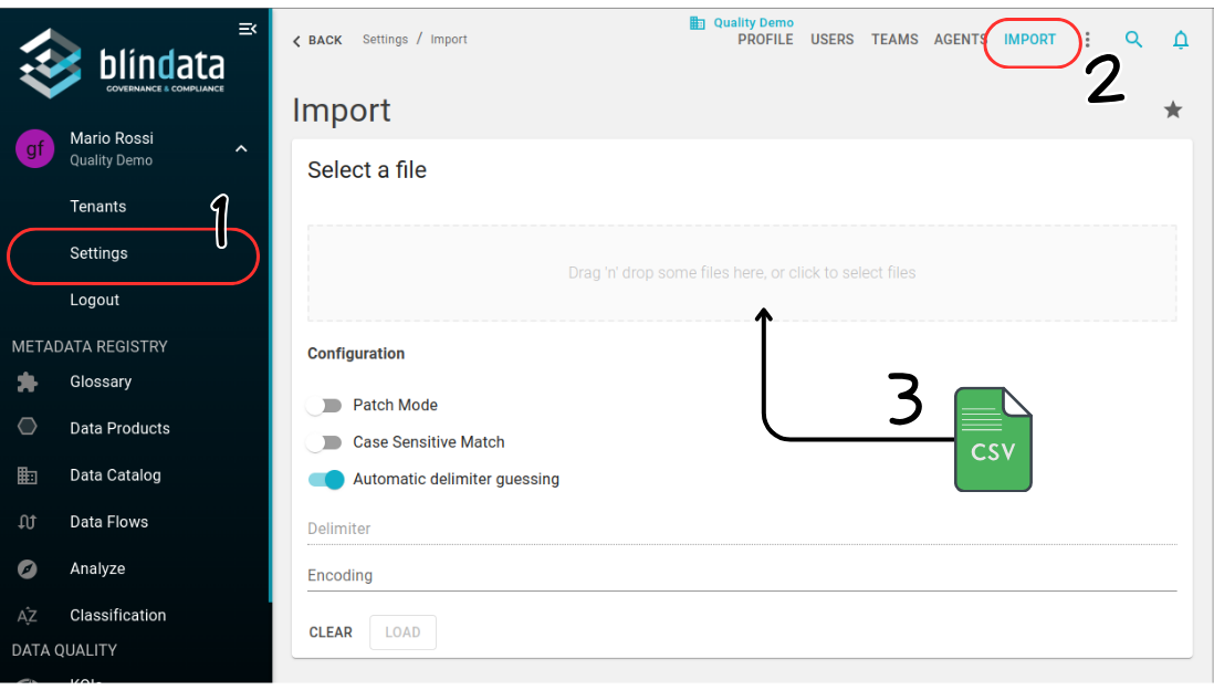
Once edited, users can upload the CSV file using the import functionality accessible under Settings → Import.
Automated ingestion via SQL crawling
When metadata is harvested with the Blindata Agent using the SQL crawling strategy, you can also ingest dataflows by configuring a Data Flows Query on the crawling job. This option is available only with the SQL strategy (not with JDBC driver) and is optional: if the query is left empty, the job imports catalog metadata only.
The query runs against the target system connection and must return one row per dataflow. Each row is uploaded to Blindata together with the other crawling results. Together with scope and name, the columns you include determine the granularity of each flow:
- System to system — provide
from_system_nameandto_system_name(or the corresponding UUIDs). - Physical entity to physical entity — also provide source and destination schema and entity name (or UUID).
- Physical field to physical field — also provide source and destination field name (or UUID).
The scope tags dataflows by the process or connector that loads them (for example, an ETL tool or a BI platform). It is used with the name as the unique identifier and can be referenced by the crawling job Automatic cleanup option to remove stale flows.
To configure ingestion:
- Open the CRAWLING tab on the source system detail page and create or edit a crawling job.
- Set Strategy to SQL.
- Fill in the extraction queries for catalog metadata as usual.
- In Data Flows Query, provide the SQL that returns the flows you want to import.
- Run a TEST to verify the row count, then RUN (or schedule the job) to upload the results.
For the full list of supported column aliases, reconciliation rules, and a real-world example (Spotfire), see Data Flows Schema . For the interface tables pattern, see Metadata import with interface tables .
Tip
Source and destination systems, physical entities, and physical fields referenced in the query must already exist in the data catalog—typically because the same crawling job (or another job) has imported them. Rows that cannot be reconciled are discarded during upload.
Automated SQL analysis
Dataflows can also be generated by analyzing SQL statements stored in query buckets. For more information, see Automated SQL Lineage .